A “repository” for various projects and ideas I have. Nothing fancy, nothing rocket-science.
-
Subscribe
Subscribed
Already have a WordPress.com account? Log in now.
A “repository” for various projects and ideas I have. Nothing fancy, nothing rocket-science.

HI, This web is super.
I will make camera board with camera module MT9D111, it´s like OV7670.
Can you send me some materials or tutorials about problematic tracking and streaming?
Or some ideas? I don´t want source codes.
Thanks for answer.
Sorry for my english, my English isn´t very good becouse I´m czech.
lazarjan@seznam.cz
Hi Lazi, glad you find it interesting.
Not sure about MT9D11, but tracking and streaming are not hardware specific.
For tracking you can take a look on “Color Segmentation” solutions available online, should be plenty of information available.
For streaming is relative simple: you can go with a very simple data streaming or can use a protocol between sender and receiver. I tried the simple streaming and it is not reliable. I had to implement a simple protocol where client is initiating the capture, then my module will reply back with a header that contain information about frame (image or blob details), size (image size/format or how many blobs are detected) then stream the data and in the end append a “end of frame” sequence.
Do let me know if this helps you or you have something specific you need help with.
Thanks. Can you help me with commumication between MCU and PC. I want use same simle protocol but It must be fast… I want sending some special symbols for identyfied pixels, frames, lines by computer… Is ATMega at 16 or 20MHz available sending 3bytes of one pixel between receiving next pixel?
Can you help me with design some simple sending protocol? And what color format is the best for capture? RGB 565 444 or YUV ??
Thanks Lazi
Hmm, not sure how practical is it. If you do a bit of math: sending ONLY 1 byte per pixel for a QVGA frame will mean already: 320 pixels x 240 lines x 30 frames = 2250 Kbytes / second, changing now to 3 bytes/pixel will means 6750 Kbytes / second. Just to stream this amount of data you will need a 55296000 bauds… There is no way you can possibly achieve this ever.
Doing the math the other way around: you are using a AT328P, if you change your crystal to 22.1184 Mhz you should be able to go to 912600 bauds or around 114 Kbytes / sec. If you decide to go with only a QQVGA (160 x 120) and will only allow you to go slightly with 6 frames per second if there is nothing else to slow you down.
As you can see, for fast data transfer, using serial port is not really a good idea. You may want to consider using SPI, that will allow you reach much faster speeds.
Anyway, for a serial communication, will suggest reducing to minimum the amount of data you plan to send: send only luminance information downsampled to 4 bit per pixel, send only information for odd pixels, use QQVGA. This will decrease the size o a frame to 4.9 Kbytes. If you decide to go even further: send only 128 x 120 pixels per frame which will reduce it even further, to only 3.9 Kbytes. At this size, you may be able to reach around 29 frames per second at 912600 bauds if there are no delays.
However, this means only data streaming, any other information sent will impact these numbers.
Maybe you should first decide what your application should do then see how to achieve that.
Hi
i would like to see the schematics & the source code is it possibile ?
Cheers
Hi, thank you for your interest in this project. You should find pretty much everything on schematic and code for this project in the blog and attached comments. I will be able to guide you if you need any help with your project.
My first idea is streaming video from camera to PC, in next time I will working on tracking or detecting objects. I read a datasheet ATMega644P and ATMega32. I want transfer data over bluetooth UART(1M – 1.8Mb/s) Is ATMega at 16Mhz possible transfer data from cam in double speed UART mode to 2Mb/s?
Can you help me with setting registers for output image format to YUV. I have mistmash in it. Some data are on page 49 http://www.uctronics.com/download/cam_module/MT9D111_SOC2010DS.pdf
Thanks your pages are very interesting.
I doubt you will ever be able to reach that kind of speed over bluetooth. Looking at the data sheet, you may be able to reach up to 2 Mbps over UART, however, not sure how reliable. Also, you keep ignoring the fact that you will need to capture and process the image before you send it out. How exactly you plan to do that?
Sorry, but I have no idea nor a way to test the registry settings on MT9D11 module… I could help you somehow on OV7670, but not on this camera.
Hi, I read datasheet and this camera have yuv(in digital YCrCb) mode, But a don´t understand how It stream data. There is writen Y Cr Y Cr (4:2:2). It 16bits at pixel? or 8bit at pixel? Can you help me with downsample this format?
Thanks for help
Hi Lazi, is actually 8 bits for Y, 8 bits for U, 8 bits for Y1 and 8 bits for V, which means about 16 bits of data per pixel but 24 bits colour depth per pixel.
There is an entire post about how to use this to convert it to RGB on PC side (https://thinksmallthings.wordpress.com/2012/11/03/ov7670-yuv-demystified/).
Hope that answer your question.
Hi, I understand. I do math and I have problem with downsampling I want stream resolution 320×240 to 10fps = 768 000 bytes and it´s to much to stream over serial port. I want to use y(4bits)U(4bits)y(4bits)V(4bits) but it´s much data. Can you help me with good method for reduce data? I have problem with English. Can you write some simle schematic of data stream ?
Thanks for your time …
I’m afraid that will not be realistic to look for that resolution and color depth, you may need to lower down your requirements or move to SPI instead of UART?
You can consider for a start to reduce from color to B&W only, for example sending only 4 bits of Y signal for each pixels, which means 1 byte for every 2 pixels. You can then alternate: on one line send odd pixel values on the following one the even ones, this will reduce by 8 times your original data while you still get good results.
Even so, doing the math: 240 lines * 160 pixels per line * 4 bit per pixel * 10 frames = 1,536,000 bauds… If you reduce the line from 320 pixels to 256 you may get 1,228,800 bauds and this is only the theoretical one, with no delays.
To answer the second part, when you are retrieving the data in original form, 2 bytes per pixel, will look something like:
...for (x = 0; x < WIDTH; x++){
clock();
byteL = readData();
clock();
byteH = readData();
line[x*2] = byteL;
line[x*2 + 1] = byteH;
}
streamLine(line);
...
will become something like:
...for (x = 0; x < WIDTH; x++){
clock();
byteL = readData();
clock();
byteH = readData();
line[x] = (byteH & 0xF0) | (byteL >> 4);
}
streamLine(line);
...
This will convert from 8 bits per channel to 4 bits per channel. To keep only the B&W information you can change in something like:
...for (x = 0; x < WIDTH/2; x++){
clock();
byteL = readData();
clock();
clock();
byteH = readData();
clock();
line[x] = (byteH & 0xF0) | (byteL >> 4);
}
streamLine(line);
...
Hope this helps.
hi, im using the lpc1769 for the ov7670. how do u actually convert the uart serial data into images?
Hi Kenneth, I’ll just stream the information from the camera (e.g.: YUV, RGB) to the serial port adding some start/end frame data, on the host side I recover the data and process it for display. Maybe if you take a look on the sample code on the host side may help (is a section containing sample code for PROCESSING and there is also the format of the data explained online). Hope this helps.
thanks for the quick reply,greatly appreciated. do u need any additional programs to output the video on the computer?
Well, the data streamed is “raw” and need processed on the host side unless you add the proper headers to each frame to match our client requirements. For performance reasons I decided to just stream raw data and do the processing on the host side, hence writing my own “driver” using processing or VB.
Dear friend,
I am making a project that have been related to processing image, i have used LPC1768 + LCD TFT 2.8″ + OV7670 FIFO and was got some troubles. I saw your project very nice and i would like your help to solve these problems. would you mind sending sample code of your project about tracking object to let me reference ?. Anyway thanks very much.
Best Regard,
Tran Anh Huy
My email: huytran.biome@yahoo.com.vn
Hi Tran, unfortunately I can not share the tracking code, however, you can find many white papers on this subject that may help you get started.
Hello!
First of all congratulations for your site and your projects.
I’m working with a OV7670+FIFO (Version 1). I’m getting troubles in order to get a synced image. The best I can get is something like this: http://www.drk.com.ar/images/forum/outofsync.png
I wait for VSYNC LOW, then for HIGH
then I pull WRST LOW, WE HIGH, then WRST HIGH and wait for VSYNC go LOW again and pull WE LOW
Hi Leandro, thank you for your comments.
Looking at your image it seems like you have 2 problems: out of sync (are you reading 1 px per line less?) and problem with your colors.
Any details on how you are reading the data from the FIFO?
I’m reading like this:
// Read reset
digitalWrite(OE, LOW);
digitalWrite(RCLK, HIGH);
digitalWrite(RRST, LOW);
digitalWrite(RCLK, LOW);
digitalWrite(RCLK, HIGH);
digitalWrite(RRST, HIGH);
digitalWrite(RCLK, LOW);
// 640×480 times:
digitalWrite(RCLK, HIGH);
dw = (uint8_t)(PINC&15)|(PIND&240); // Get data
digitalWrite(RCLK, LOW);
In fact, I read the whole frame as a chunk of 640×480 bytes. I don’t stop between lines. If I’m missing a pixel per line, that mush be happening during FIFO writing cycle. But that’s completely automatic as far as I know.
looking at your code you seems to be reading 640 x 480 bytes, right? But the data is 2 bytes / pixel, which means 640 x 480 x 2. Assuming that you are actually doing that since I can see (somehow) the image you captured, the only thing left is the way you display the picture on the other end.
Now, looking at OV7670 datasheet, AL422 data sheet, page 12, diagram 15, your code supposed to be more like: VSYNC FALL => WE = HIGH -> W WRST = LOW -> delay few WCLK -> WE = LOW -> WRST = HIGH, or else to make your life easier just feed VSYNC to WRST, handle only WEN in your code and be sure you change COM10 accordingly (see details here).Not sure if this will solve your problem, but definitely will make it easier. Please do remember that your WEN is active in HIGH not in LOW (WE = WEN NAND HREF). Signals can be seen here.
Also, if you do have long delays in handling the WE and WRST from the moment VSYNC falls (17 lines or 0.5 ms) then you will loose also pixels since you start writing after the data start coming.
I can’t reply to your last comment so I’m using this one. I stopped to check the two bytes issue. I used a non-FIFO version months ago and I was able to get images of two or one byte per pixel. But the AL422B has 3Mbits so I can’t store a frame of 640 x 480 x 2. Right now I’m configuring the sensor for one byte per pixel output. Will let you know what happens.
Hola buenas, primero de todo decirte que encuentro asombroso todo el trabajo que llevas hecho con el sistema de tracking.
En segundo lugar quería comentarte que estoy trabando con un proyecto parecido que involucra una cámara de igual funcionamiento, concretamente OV6620. Estoy trabajando en una fpga de momento mi objetivo es mostrar directamente en pantalla por salida VGA el streaming de vídeo. Hasta aquí bastante diferente a tu proyecto.
Ahora bien , en la parte de programación C (donde tengo que transformar el flujo de datos de la cámara en una imagen para VGA) aun no he conseguido una imagen bien definida.
Por eso quería preguntarte si podías ayudarme, ya sea con formato RGB o YCB en el código necesario para transformar ese fluyo de datos en un array bien ordenado que forme la imagen. Lo que es la sincronización de Vsync Href y Pclk ya esta bien definida.
Muchas gracias por adelantado,
Un saludo
Hola Aitor, sorry, my spanish is a bit rusty, I’ll post the answer in english instead.
I guess you are not using a FIFO but rather read all straight from the camera. Since you only want to capture and stream, you can try to use VSYNC and HREF as external IRQs: VSYNC will determine the new frame, HREF the new line.
If you check VGA frame timing diagram in OV data sheet, will see that there is a 144 pixel clocks between each HREF rising edge within a frame, may be enough to stream a data line to your host.
Basically something like:
while (1)

  if (VSYNC == FALL){

    stream(START FRAME);

  }

  if (HREF == RISE){

    from (i=0; i<640; i++){

      lineBuff += capture (pixel);

    }

  } else if (HREF == FALL) {

     stream(START LINE);

     stream (lineBuff);

  }

  if (VSYNC == RISE){

    stream(END FRAME);

  }

}
Of course, using interrupts will be better. Hope you will have enough time to stream all your data at the end of each line. Can also use the 30 line “dead time” between last HREF in a frame and the HREF in the new frame, however, there will be a 1 frame delay in this case…
On the host side your code should be able to identify the START FRAME/LINE and place the data accordingly. However, adding a START/END at each line will mean additional overhead, something you may want to consider.
Hope this helps.
Sorry, I have no problem with English but I don’t really know why I posted in Spanish!
Thank you! What you explains is what more or less I am already doing! My problem is to sort out all this amount of data at the same time I am receiving it. since the rgb mode is outputted in a bayer matrix format and so. Then I am trying to write an easy algorithm to do it.
Thank you again
I would like to clarify that I want to sort out to obtain the R G and B component of each pixel. :)
Hmm, looking at your camera data sheet seems you really have a lot of work to do, is very different from the OV7670 module.
If I get it wright, you will need to read 2 consecutive lines and you will have to combine them to get the result. The simplest way seems to be using YUV mode, read Y from first line and UV from second line (table 7), then use the YUV -> RGB equations to get the final RGB format.
Or switch to a OV7670 camera, that can output directly RGB565 or RGB555 as 2 consecutive pixels which is what you want.
Hello again, I have been reading the specifications of your camera OV7670 (which some days ago after being reading your site I bought one on ebay, it is supposed to be with me in a week). I have noticed it has a range of data formats that my camera doesn’t.
So, I only have a question regarding the format rgb 555 and rgb 565 in the model OV7670 with FIFO. Do each 2 bytes represent one pixel of the screen? I mean, is it not necessary to extrapolite the bytes from the bayer matrix?
If the question is affirmative I will be bery happy! Sorry for posting three times. Thanx!
Yes, you can configure it to dump RGB565 (Figure 11) or RGB565 (Figure 12) as shown in OV7670 datasheet, page 9. Check on COM7 and COM15 registries for details.
Exellent!
When I receive my OV7670 I’ll tell you about the results. And also if you think could be interesting for you o anybody, I can share my project, fimilar to yours but on a Spartan 3A – DSP
Keep working! :)
Sounds great!
I have no experience with FPGA, but sounds like a good way to go. Wish I had the budget to invest in a FPGA development board…
Good luck with your project, let me know if need any help.
Hello again, my cam isn’t here yet, maybe in a couple of days. I have been adapting my code and it is the core of the C program to stream the video in RGB444 mode. I only would like to ask you if it seems okey.
Thank you in advance!
while(1)
{
while(!VSYNC);
while(VSYNC); //New frame available
for (row=0; row<ROWS; row++)
{
while (HREF);
while (!HREF); // New line available
for (col=0; col<COLS; col++)
{
while(PCLK);
while(!PCLK); // New byte available
pixel_row[col]=(DATA&0x0F)<<8; // Gets the red component of the pixel
while(PCLK);
while(!PCLK); // New byte available
pixel_row[col]=pixel_row[col]+DATA; // Gets the green and blue components of the pixel
}
for (col=0; col<COLS; col++) // Prints the whole row
set_pixel(col, row, pixel_row[col]);
}
}
Hi, you mentioned that you ordered the OV7670 module, if is the one with FIFO then your code will be different, you can get away with most of these checks.
If is not the one with FIFO I’ll probably use external interrupts for VSYNC and HREF instead of while loops. Any details on the MCU you are planning to use?
If you are using AVR the code may look like:
ISR (INT0_vect){

    cli();

    stream(FRAMEHEADER);

    startFrame = true;

    lineCount = 0

    sei();

}
ISR (INT1_vect){
cli();
startLine = true;
lineCount++;
pixelCount = 0;
sei();
}
int main (void){
// initit ports, state, etc
intitBoard();
initCamera();
// int 0 - VSYNC FALL
MCUCR = (1 << ISC01);
GICR |= (1 << INT0);
// int 1 - HREF RAISE
MCUCR = ((1 << ISC01) | (1 << ISC00));
GICR |= (1 << INT1);
sei();
while (1){
if (startLine){
startLine = false;
while (pixelCount < LINEWIDTH){
// first byte
while(PCLK = 0);
lineData[pixelCount*2] = DATA & 0x0F;
while(PCLK = 1);
// second byte
while(PCLK = 0);
lineData[pixelCount*2] = DATA & 0x0F;
while(PCLK = 1);
pixelCount++;
}
stream(LINEHEADER+lineCount);
streamLine(lineData);
stream(LINEEND);
if (lineCount == FRAMEWIDTH){
stream(FRAMEEND);
}
}
}
}
Well, more or less. Can loose the start/end line headers if you want, but may be helpful to reconstruct the image on the other end.
One thing to keep in mind is that your PCLK speed is important. If you feed the camera with a 12 Mhz and set CLKRC register with no prescaler, then you need to be sure your MCU can handle that kind of speed: have to check how many MCU cycles will you be using in reading every pixel and see if is enough…
Thank you!
Sorry but I have another question.. ^^
I already have here the cam but I am having a problem with i2c,
Though I am not actually sure which is the problem I think is related to the voltage or the pull-up resistance.
The first question is about Do I need to supply a xclk to use I2c?
And the second one, Which resistance and connections I need to have to use it properly.
I have use the same scheme I had with my old camera which works well.
see u :)
If you are using the FIFO version you won’t need the XCLK, if is the non-FIFO one then you will need the XCLK.
I am using a 10K pair of resistors on I2C bus and works fine, however, i am using short tracks from MCU to the camera. Hope that helps.
Hello again, I am almost there.
As I told you I have started all along with an Arduino Due.
I managed to set and VGA output, I have OV7670 feeded with and 10Mhz clok and the I2C is working. I can read the full bank and modify the ones of my interest.
Now I am implementing the code, I have the interruptions working as well. Now I am working y the main code. I was reading your example you give me above and I have a question,
If I am working with rgb444 the code must be like this:
while(PCLK = 0);
lineData[pixelCount*2] = DATA & 0x0F;
while(PCLK = 1);
// second byte
while(PCLK = 0);
lineData[pixelCount*2] += DATA;
while(PCLK = 1);
pixelCount++;
I only have change the way we are getting the second byte.
Thanks
It’s Done! (More or less)
First Time I can see me through the camera!
Not good quality, I’ll keep going.
Here my first ugly result!
Once I improve my sep-up I show you some photos if you found it interesting
Cool! So you are now getting VGA data then streaming to your VGA controller to a TV/monitor?
Cool!
Easier will be streaming, can get it done easy over serial port, but will be too slow, but i don’t see why would you want to stream full frame to a PC, you can achieve the same thing with a cheap USB camera.
For SD card you can look for FatFS, download the code, connect your SD card adapter over SPI and you are almost done.
Not sure on what performance are you looking for, but you should be able to get 600 to 1200 Kbytes / sec for SD card, using UART can’t go higher than 100+ Kbytes / sec…
Yes, it’s the set up without the camera

Then I am getting the data and sending through the vga to the monitor!
Now I also would like to get the image to the pc or to and sd card.
Which of those opcions would be easier ?
For the first opcion (getting and streaming in the pc) which would be te keywords in which I have to focus in order to get information and eventually do it? (I have no ever done something like this)
Thanks!
I would like to implement the streaming in order to know what are the real image I am capturing since the vga controller don’t have a very good quality and won’t be able to improve much more.
There is some somewhere prepare for streaming the video, or I’d better try with processing or something like this?
Thanks, many thanks for everything,
If you just want to see, to keep it fast, stream lower resolution B&W. Going QQVGA (160×120) @ 4 bits/pixel may give you more than 10 fps when streaming @ 921600 bauds. Adding color will means 4 times slower.
Anyway, you can stream frame by frame, using some simple protocol (e.g.: start frame header+raw data+end frame header), then on host side look for “start fame” and once you got it read the data. Is fast and simple but prone to errors. You can complicate by adding “start line” header, etc but this will add an overhead.
Another option is to just pull the data: send a frame request from host, your board will return the frame embedding some control headers, your host will read all available data and can discard the frame if data is incorrect. Is slightly slower as you need to keep pooling frames, but is safer.
Yet another option for high speed and minimal errors: stream over SPI/SSP port, is definitely faster and practically no errors. However, you need SPI/SSP port on host running at high speed…
Thanks! Now I have a clear idea of what I am going to try.
I would like to ask you if you could let me know which are the registers involved in achieve an QQVGA resolution. I am a little bit confused becaus of there are a lot of registers with talk about scaling the signals but actually I am not sure whether or not these scaling would affect the resolution. I am trying right know!
If I achieve it before you read it I’ll post here in order not to bother you!
Best! Aitor
You can take a look on this: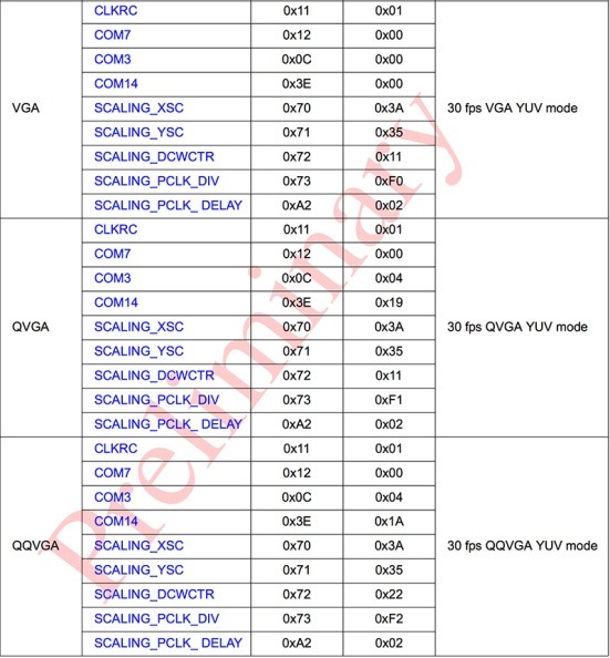
Done qqVGA, working!
Great! Just posted the list of registries too…
I have finished writing my first library in order to arrange a little what i have already done! Then, I have been looking for an easy example of processing I can use to create my processing code to get the streaming of the camera through serial.
I haven’t find any example like that, I saw with comercial cameras, thousand of leds examples and image processing but I was looking.
I had promised not to ask about this but .. Could you share your more basic code of processing in order to get the video without any extra?
All I have doing is for a important project at university. Once I finish I’ll write a thank you page in there!
LOL!!! No worry about that, for me this is just fun ^_^
Ok, real stuff now! Well, you could see there is a code sample already in project section, however, will “dedicate” a new post, posting in comments mess-up the formatting ;-)
Sorry for being here again, if you don’t wanna waste your time I’ll understand! ^_^
I already have the non-fifo version (And waiting for the FIFO version to arrive). And also I managed to get an proper scope.
I am having some problems with my fpga solution so I am going to trying another thing just in case finnaly I have to leave my first option.
I have thought to begin with an arduino due. My plan is, first of all to create a vga controller. I will no have problems with this. Once it works propperly i would like to stream the camera to the vga. And if it works later i would like to follow a little your project.
So I just wanna ask you some stupid and rapid questions.
– Before I start with the color detection, Will I need some extra Hardware? Maybe a memory between the camera and the arduino? Or all this stuff is worked out while the pixels are coming?
– I have more or less the same question about pc streaming. Can it be done only with the arduino and the cam? I can’t find if you have posted somewhere how are you doing this with processing.
Thanks a lot. Keep working like this
Best,
Aitor Sánchez
You are sure not wasting my time, no worry!
Not sure why you need to create a VGA controller, guess that is something to do with your project rather than capture/tracking?
To answer the questions you asked:
– I did use a FIFO between the camera and MCU, more to unload the MCU during image capturing process, also that allows me to do do image processing for each line since the MCU I was using initially had only 1 Kbyte or RAM;
– Considering the fact you want to use an Arduino Due (Cortex M3 @ 84 Mhz, 96 Kbytes RAM) guess should not be a problem to do pretty much anything you want. For comparison, my CTS module is using a Cortex M3 @ 72 Mhz with only 8 Kbytes of RAM to do tracking and streaming and I am limited only by the serial speed…
There is a section covering the code for Processing on my project details.
Thank you! A incredible valuable response as always!
Then i guess I will have no problem with Arduino Due.
With the FIFO between camera and MCU do you mean the FIFO version or another extra FIFO?
Another couple of questions. First of all, do you have a AVR code to show me like the one above but for the FIFO version this time? And the last thing for today, once you were thought the process of learning how to tracking colours etc… do you have any special link book or whatever to begin to learn how to have to be my code to do it?
Best,
Aitor
PD: I hope one day I would be able to help others beginners as you are doing with your blog :)
You are always welcome!
Only with FIFO between camera and MCU.
Will try to look for it but most of the code for handling the FIFO, including the diagrams and the captured signals are already posted on the blog in “comments” section, maybe you want to check here, here, here, etc.
Actually I “learnt” just by experimenting, started as a fun project more than a year back (see some details here). Anyway, there are plenty of materials available online, just look for “colour segmentation”, “connected component labelling”. Once you get the algorithm working you can focus on speed. One very interesting article I found is this.
Hi!
I want to make some experiences with camera plus machine (whatever it will be at the end, don’t know it yet). Your boards sound quite interesting. Can you please tell me how to get one of them, what the prices would be etc. I tried to get an overview through this site. But until now I wasn’t very successful. :-(
Thanks in advance!
Hi Dayzz,
Sent you a mail with details.
Hi Again!
I have found some free time to work with the arduino solution again, this time I already have the fifo – version . v3 (I have not found which is the different with the v2)
I would like to show you my main loop, which I think is eassy to read and undestant.
void loop()
{
//WRITING ON FIFO
OE_SET; // Output high impedance
WEN_CLR; // Enable writing
onFrame=true;
while(onFrame); // The present frame ends
onFrame=true;
while(onFrame); // An entire frame have been saved on the FIFO
WEN_SET; // Disable writing
RRST_CLR; // Reset reading pointer
RCLK_CLR; // Waits for 2 RCLK to reset
RCLK_SET;
RCLK_CLR;
RCLK_SET;
RCLK_CLR;
RRST_SET; // Pointer is Reset
OE_CLR; // Enables reading
//PULLING DATA
for(int i=0; i<COLS*ROWS*BYTES;i++)
{
RCLK_SET;
frame[i]=DATA;
RCLK_CLR;
}
//Do somithing with DATA
}
If y print by serial the Data if I am not wrong I woulrd have to read 0x0,0x80, repeteadtedly. But the numbers dance a little, I mean maybe I get 0x0,0x80.0x1,0x81,0x0,0x79…0x3,0x82… etc Is it normal?
In order you can answer better if I am doing okey I have take a photo of the signals of the cam.
https://www.dropbox.com/sh/bsxky8jewrnjxj5/E8z-Zj8ZOO ech photo is named with their signal name.
Thanks in Advance! (working with arduino DUE)
No Idea on V3, sorry, to expensive to buy them anymore. However, your code while may work is far from clean… Instead:
– I’ll just keep OE always on LOW unless you are sharing the bus with something else, are you?
– I’ll use a “while” instead of “for” (less cycles)
– I’ll pre-calculate the number of bytes I need to read rather than calculating it every time
– Setting WEN to High is actually enabling writing, check your module schematic (WEN and WE are not same signals)
– I’ll take a better look on AL422 data sheet, on camera module schematic and try to understand my application, this may make a huge difference on final speed…
Nice waveforms but not sure how may help. If you were using 2 or 4 channels and use a signal as reference may make more sense. Try using a logic analyser, use VSYNC as reference then you will have a better view of what is going on ;-)
When I started working on this project I took this “snapshot” and contains pretty much the details i needed that time:
Thanks!
– Your’re right I dont need to be changing OE, now is always LOW
– I have replace the for loops. Now:
i=0;
while(i<frameLength)
{
RCLK_SET;
frame[i]=DATA;
RCLK_CLR;
i++;
}
– I have have precalculated the Lenght -.-' !
– As you have supposed, I had confused wen with we, Now I have realised go to a nand gate with HREF, then must be first High and later Low
– With all this changes now I am reading the bytes without the "dande" above ! :)
Managed to write a photo to SD and later convert to png file.
Result with colobar enabled QCIF resolution and YUV422 mode.

Personal photo with Colobar disabled

Registers modified:
write(0x12,0x80); // Reset all the values
write(0x15,0x02); // VSYNC inverted
write(0x11,0x82); // Pescaler x3 (10 fps)
write(0x0C,0x08); // Enable escaling
write(0x12,0x08); // QCIF
write(0x42,0x08); // Enable Color Bar
Any idea what’s happening? Thansk :)
Beside the fact that you’ll need to focus your camera first? Sorry, just kidding :-) those modules does not come pre-focused, so you’ll need to un-tighten the small screw then turn the lens till you got a sharp image.
The color-bars looks pretty fine, guess beside setting up the white balance your image should turn up fine once get it focused properly.
After a few attemps with the focus I get this!
(The photo is a tribute to you)
But, as you can see… I am missing the colors..
Hey! Is not fair! That’s my Mario!!! Also looks like my scope…
The colors? If you are using YUV, try swapping U with V for a start. Then go back to your datasheet, you missed few RCLK cycles ;-)
Aleluya! a Red Mario!
https://www.dropbox.com/s/wjxywndjothjpcf/WIN.png :)
so, i was right?
Yes, I was doing yuyv intead of uyvy translation ! Now I am working in a library to save directly in bmp format in the SD because I war doing this in the PC side. Once It works I will go back to the stream issue and so!
:)
That is easy. If you set your camera to send RGB, will be piece of cake!
Yes it has been easy, porting rgb444 to bmp.
https://www.dropbox.com/s/e81ut9yqocio33o/MALOTE.BMP
But I can understand why I am “shedding” thas last pixel of each row! Since I am getting the entire frame in a buffer.
Hello another time!
Today I am here just for showing where I am and thank you another time!
After the bmp file succeed I managed to get the streaming with processing (15fps BW and 10 fps RGB444/YUV422 with QQVGA resolution)
Later I bought two servo motors and I have started with the tracking, I am using blob detection approach getting the average position of the color RED BLUE or GREEN working with RGB444, I can do it 15 times/second.
Then with that with a ugly control I achieved this:
Now I gonna try some better control with PID. And also to try to find how can I do it with YUV, I have read this would be more affective.
Merry Christmas
Nice! Not bad, with some improvement is quite promising!
Merry Christmas to you too!
m using Arduino UNO to read the values of OV7670 registers.. Im using the Wire library..
Reading the registers works fine
int addressread = 0x21;
int address = 0x1;
int data = 0x3;
——————–read code—————
Wire.beginTransmission(addressread);
Wire.write(address);
Wire.endTransmission();
Wire.requestFrom(addressread,1);
while(!Wire.available())
{
}
int c = Wire.read();
Serial.println(c);
————————————————
but when I am writing registers, it doesn’t work
——————-write———————-
Wire.beginTransmission(0x21); // i2c slave address
Wire.write(0x1); //register address to write
Wire.write(0x3); //data to write
Wire.endTransmission();
———————————————–
I executed the above write function, and when I read back, it doesnt change.
Please help
Thanks
Maybe I miss something but according to my OV7670 data sheet (page 11) supposed to be 0x42 for writing and 0x43 for reading…
Hi there nasulica!
I have recently found this blog of yours and truth be said, I got dizzy surfing through the complicated stuff that you have managed to bring to life!
I found your blog while I was trying to make my new OV7670 with AL422 FIFO module(v.3) work with ArduinoMega2560. I managed to get a single image and even filter it with a blue filter without any complications but then I noticed that I cannot get another frame out of the camera module! After a quick glance at the datasheets, I realised that I was not operating the camera the way I should have and I tried to do it the right way but this time, I even failed to get the first image out of the module.
I put the VSYNC pin to an interrupt and when the rising edge arrives (VSYNC is inverted in order to trigger WRST between frames) I do the following:
if (capture) {//write enable if capture request arrives
WEN_SET;
capture = false ;//write for only one frame
} else {
WEN_CLR;
if (busy) {
busy = false ;
}
then I reset the read pointer by doing:
RRST_CLR;
//delayMicroseconds(1);
RCLK_CLR;
//delayMicroseconds(1);
RCLK_SET;
//delayMicroseconds(1);
RCLK_CLR;
//delayMicroseconds(1);
RCLK_SET;
//delayMicroseconds(1);
RRST_SET;
finally, I read FIFO output 2 times for every pixel with the following code to send 120*160 RGB565 data to my computer through serial bus:
int c;
RCLK_SET;
c=DATA;
RCLK_CLR;
return c;
I am stuck at this point right now as the image I’m getting now looks like noise. Could you please give me a little bit of insight about this problem? Thanks in advance…
FYI: you have a brand new fan! :)
Hi Strider, good to know!
Since you manage to get a frame from the camera your FIFO read part should work. Looks to me that the problem is on the writing part.
Try setting WEN to HIGH at the very beginning of your loop then only after retrieve the image to set it LOW.
Hi,
Looking for building a very similar board but able to reach 100 fps (for example woth OV7251). Detection situation would be stable background and idneitfication of a single color point.
Could you help ? this can be funded,
Best regards
Seb
Hi Seb, will send you an email for details.
Hi
I am a Computer Science student. I’m working on a project to get camera readings to PC via an Arduino. The camera I am using is an Ov7670 with 22 pins in it. I think it’s the one that has FIFO in it. I have searched the web alot to try and find out about how to connect the pins of the camera module to the arduino and check a sample code.
Can you’ll help me????? I am from a software engineering background!!!!
Hi Shabir, will you be able to explain more about your application and your expectations?
I think you may be able to capture a low resolution frame, however, you will need to take into consideration several factors (e.g.: how you transfer the image to the PC? if is UART, will you have enough enough memory to store an entire frame or a line? if you transfer a line, what UART speed are you planning to use? will you have time to send a line of data before you start scanning for the next line? etc).
Assuming that you already thought of all this and you know the limitations of your host MCU (e.g.: which arduino?) i will start by connecting: HREF and VSYNC as INT0 and INT1, inject a 12/24 Mhz clock into XCLK, connect the SCCB to I2C port on Arduino, PCLK to an IO pin, your data lines to the remaining available IOs on your MCU.
Write your code to handle your SCCB protocol, program the camera in QQVGA or even lower resolution, change the clock divider to get a very low frame rate, write your interrupt routines to be triggered by VSYNC and HREF.
the logic will be pretty simple:
while(){

  If VSYNC going down{                     // start frame

    If HREF going up{                      // start line

      while (cPixel  lineBuff[cPixel++]   // 2 bytes / pixel

        }

      }

    }

    UARTsend(lineBuff)                    // send a line on UART

                                           // when HREF is down

  }

}
This is only high level. Once your logic works fine, you can increase the frame rate to a decent value.
However, due Arduino limitations you will need to remember that UART speed can not go too high and the speed will be determined very much by several factors. I will consider ignoring Arduino boot loader, replace the crystal to a 22.188 Mhz, connect CLKOUT to XCLK and program the fuses accordingly, write the code using AVRstudio, etc. This will help you get a pretty decent speed ;-)
First of all thankx alot for your reply.
The MCU: Arduino Uno
The camera I am using has 22 pins. Its a Ov7670 with FIFO. It doesn’t have pins called XCLK and PCLK. The pins it has got are – GRN, VCC, SIOC, SIOD, VSYNC, HREF, D0 to D7 (8 pins), RST, PWDN, STR, RCK, WR, OE, WRST, RRST…..
I am still a starter, so I don’t know wheich pins goes to which one in the arduino. Also I am trying to get the data via and arduino and send it to a rasberry Pi for processing using OpenCV. Its for a robot to identify certain messages on its way. So I want to read capture images, pass it to Rasberry and process it in there using OpenCV…… Can you help…..If you can help me connect the Camera module to arduino and get the data captured as an array I can do the rest about passing it to rasberry and all…..
Hello,
Maybe you remember me, I was bothering you some time ago with one project.
Today I am here to ask you for another favour.
I would like to know where do you order yours pcb and so. Or if you don’t have any site where you usually order, any advice will be very welcome.
Thanks in advance :)
BR,
Hi, I order my PCBs from DFrobot.com. They are quite good and very helpful.
Thank you
cheers
Hey, i am working with OV7670-fifo-v3 and arduino mega. I also have with me Tiva C series TM4C123G eval board. I went through your posts and my issues currently is that the camera module does not have WRST pin. Also I need to live stream. I would appreciate your help.
Thanks.
Hi Maria, that module is using WSYNC connected to WRST. This way when /WE is active all the time you can use it to stream video.
Will this help?
Hi Nasulica,
Very informative site. Thanks!
Few words about yourself will be nice to hear :)
Hi Nasulica,
I am working on an educational project for high-school students where we would like to use OV7670 get the image of a modelled-traffic light, then process the image to recognize if it is green, red or yellow so that the robot can move accordingly.
For getting the image from camera to Arduino is not complicated and many tutorials on the internet. However, can you please help to guide how can I process the image with an MCU like you did with CTS module? Is it hardware matter because I am an mecha-tronics engineer not an electronics engineer, I have zero knowledge on developing an electronic board.
Have you ever thinking to make your CTS an open-source (both hardware and software) so that more people can work on improving its performance.
Thank you and looking forward to your answer.